Engineering data policy
This page describes engineering decision factors. Final recovery, membrane selection, pressure, pretreatment, power demand, water quality, and container layout must be confirmed from raw-water analysis, site conditions, and the system design basis.
What Is a Containerized RO Plant?
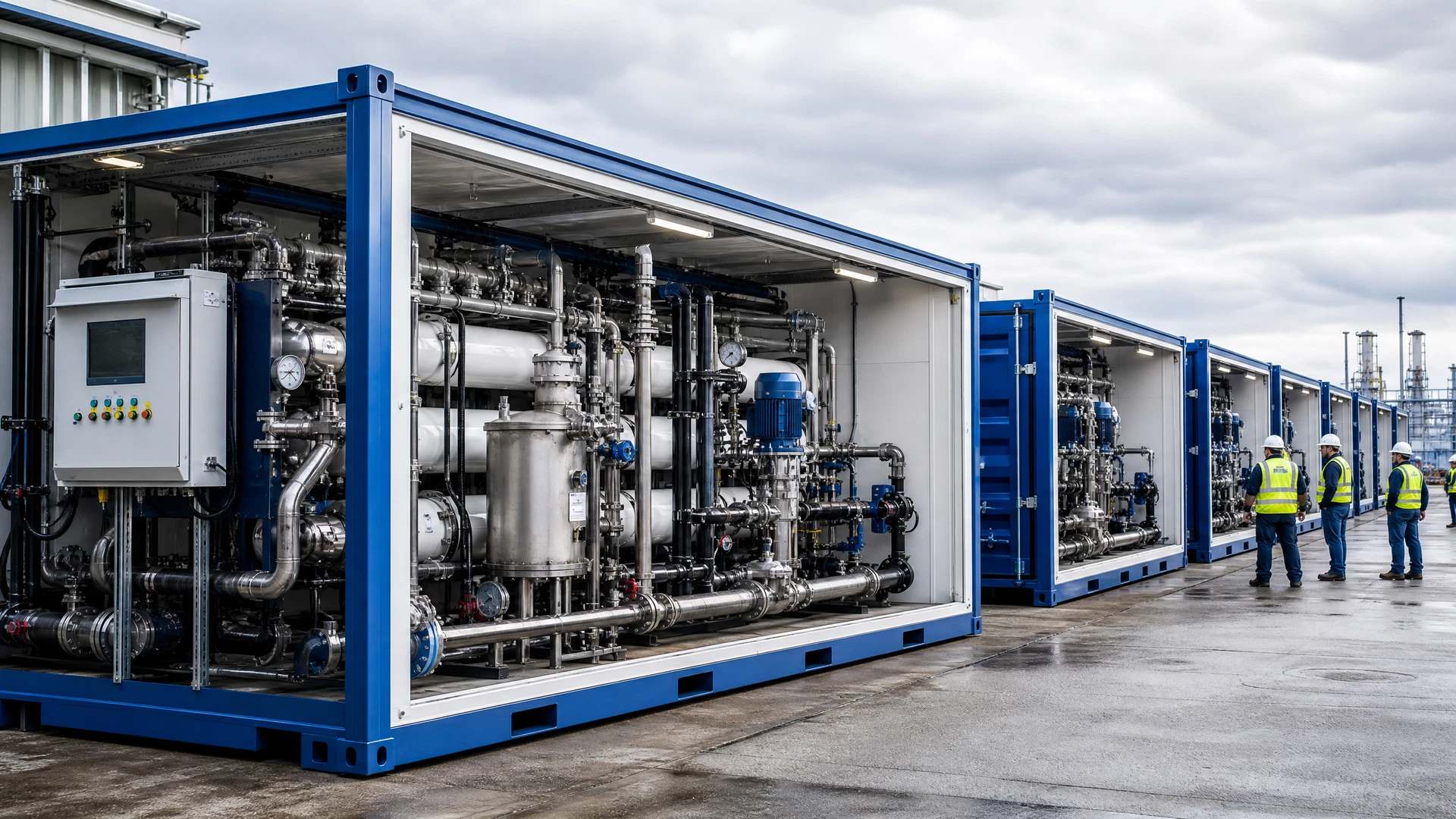
A containerized RO plant is a reverse-osmosis treatment system packaged within, or designed around, an ISO shipping-container envelope. The container can house selected pretreatment equipment, pumps, membrane pressure vessels, chemical dosing, instrumentation, electrical distribution, a control panel, and service access. Depending on the duty, some equipment may sit outside the container or occupy a separate container; the physical arrangement is part of the engineering design rather than a universal product specification.
The packaging approach is useful where factory assembly, repeatable interfaces, transport planning, weather protection, or limited site construction are important. It does not remove the need for civil works, source-water intake, drainage, product-water storage, power, operator access, concentrate management, and commissioning. A viable concept therefore defines where the container boundary begins and ends, as well as the responsibilities for each external interface.
- Factory-assembled treatment train
- Transportable enclosure and defined site interfaces
- Design based on feed-water analysis
- Expandable when multiple modules are appropriate
When Containerization Adds Engineering Value
Containerization can shorten on-site assembly when the treatment package is largely built, wired, and checked before shipment. This is particularly relevant for remote sites, temporary facilities, islands, mining camps, construction projects, or phased deployments where local fabrication capacity is constrained. It can also create a controlled environment for electrical equipment and operators in locations with dust, humidity, wind-driven spray, or significant temperature variation.
A container is not automatically the best option for every project. Large pretreatment trains, high flows, unusual access constraints, permanent municipal works, or equipment requiring wide maintenance clearance may favor a building, an outdoor skid arrangement, or a hybrid layout. The correct comparison considers logistics, erection time, local labor, operational access, climate protection, future expansion, and the cost of integrating supporting infrastructure.
- Remote and logistics-sensitive projects
- Rapid-deployment requirements
- Temporary or phased water supply
- Hybrid layouts for larger pretreatment duties
Feed Water and Product-Water Design Basis
Reverse osmosis design begins with the feed water. A laboratory analysis and site description help establish the likely fouling, scaling, corrosion, biological, and hydraulic risks. The engineering review normally considers the source type as well as available chemical and physical information, such as conductivity, pH, turbidity, suspended solids, hardness, iron, manganese, silica, sulfate, chloride, organics, oil, microbiology, and temperature. Results from a single sample may not describe seasonal or operational variation, so known variability should be stated.
Product-water requirements must be defined in the context of use. Drinking-water distribution, process-water use, boiler feed, irrigation, reuse, cooling-tower makeup, and downstream polishing each have different quality, reliability, monitoring, and post-treatment considerations. The design should state the target use, flow profile, operating hours, storage strategy, and applicable local requirements. Final treatment performance is project-specific and should not be inferred from an equipment photograph or generic capacity label.
- Raw-water source and laboratory report
- Required permeate duty and operating hours
- Product-water use and quality objective
- Expected seasonal or source variability
Pretreatment and RO Process Selection
Pretreatment protects the RO stage by reducing suspended solids, colloids, oxidants, metals, biological activity, or other contaminants that can damage or foul membranes. The appropriate sequence may include source screening, clarification, media filtration, activated carbon, softening, oxidation and filtration, ultrafiltration, cartridge filtration, chemical dosing, or another project-specific process. Selection depends on the actual source water, its variability, the target recovery strategy, and the operator’s ability to monitor and maintain the equipment.
The RO stage then separates a permeate stream from a concentrate stream under pressure. Array configuration, membrane family, pressure-vessel arrangement, pumping, chemical dosing, flushing, cleaning provision, instrumentation, and control logic should be established together. Recovery, salt passage, operating pressure, energy demand, and cleaning frequency are not fixed container attributes. They depend on feed-water chemistry, temperature, pretreatment performance, permeate requirement, membrane selection, and the operating design.
- Pretreatment matched to source-water risks
- RO configuration matched to hydraulic duty
- Cleaning and flushing planned at concept stage
- Concentrate management identified before procurement
Container Layout, Utilities, and Interfaces
A practical container layout must allow operators to reach valves, filters, pumps, electrical panels, chemical connections, and membrane vessels safely. It must accommodate lifting and handling considerations, internal drainage, ventilation, lighting, cable routing, chemical segregation, noise control, and maintenance paths. Access doors, removable panels, forklift pockets, lifting points, and external connections should be resolved against the project logistics plan rather than assumed from a standard layout drawing.
The site package usually requires more than the container itself. Typical engineering interfaces may include raw-water feed, pretreatment backwash discharge, permeate outlet, concentrate discharge, chemical supply, electrical incomer, earthing, communications, ventilation allowances, foundations or support pads, and product-water storage. Interface drawings make responsibilities clear between the equipment supplier, EPC contractor, civil contractor, and plant operator. This prevents late-stage changes that can affect installation duration and operability.
- Operator and maintenance access
- Electrical, drainage, ventilation, and chemical safety
- Source, permeate, and concentrate tie-ins
- Civil, storage, and communications interfaces
Controls, Testing, Commissioning, and Maintenance
Control philosophy should match the level of supervision available at the site. The system may need local operation, alarm handling, interlocks, remote status signals, historian integration, or a defined remote-monitoring arrangement. Instruments and alarms should support safe operation and meaningful troubleshooting, including flow, pressure, conductivity, tank levels, filter differential pressure, and other parameters selected for the particular treatment train. Functional requirements should be listed before panel design and software development.
Factory testing, shipping preparation, installation checks, wet commissioning, operator training, and maintenance planning are separate stages. A factory acceptance approach can verify defined functions before shipment, but it cannot substitute for site acceptance under the actual water source and external utilities. The maintenance plan should cover consumables, calibration, pretreatment servicing, membrane cleaning triggers, spare-parts strategy, operator records, and escalation when source-water conditions change.
- Control narrative and alarm philosophy
- Defined factory and site acceptance scope
- Commissioning against actual source water
- Planned spares, records, and cleaning strategy
Information Needed for a Technical Proposal
A useful technical proposal starts with a clear design brief. At minimum, provide the water source, available analysis, required product-water flow, intended use, operating schedule, country and installation location, power supply, climatic conditions, site constraints, and expected delivery schedule. If drawings, existing equipment details, or an RFQ specification are available, they help identify tie-ins and clarify where the supplier’s scope should begin and end.
Where water analysis is incomplete, the engineering team can identify the information needed before final design. A preliminary concept may still be discussed, but its assumptions should be stated clearly and revisited before equipment selection or performance commitments. Sending the available data early is more useful than selecting a generic unit based only on daily capacity, because it allows pretreatment, RO configuration, post-treatment, container size, and operating interfaces to be evaluated as one system.
- Send water analysis
- Define capacity and product-water objective
- Confirm utilities and installation environment
- Share drawings and technical specifications
Typical Process Logic
Engineering Input and Design Considerations
| Parameter | Design consideration | Required engineering input | Data status |
|---|---|---|---|
| Feed-water source | Defines contaminants, variability, intake approach, and pretreatment risk. | Source description and latest laboratory analysis. | Feed-water dependent |
| Required permeate duty | Sets flow profile, storage strategy, operating hours, and train redundancy. | Required flow and production schedule. | Project-specific |
| RO recovery | Balances source-water chemistry, concentrate management, and operating risk. | Complete water analysis and discharge constraints. | Feed-water dependent |
| Pretreatment train | Protects membranes from suspended solids, oxidants, metals, or biological fouling. | Water analysis, site history, and target RO operating conditions. | Project-specific |
| Container arrangement | Must preserve access, lifting, ventilation, drainage, and maintainability. | Logistics route, site plan, equipment duty, and utility interfaces. | Project-specific |
| Membranes and pumping | Selected from hydraulic duty, salinity, temperature, pressure, and service strategy. | Confirmed design basis and manufacturer data. | Manufacturer confirmation required |
Frequently Asked Questions
Can one container include all pretreatment and RO equipment?
It can for some duties, but the answer depends on source-water treatment needs, flow, maintenance access, storage, and logistics. Some projects require external pretreatment, a second container, or a hybrid skid-and-container arrangement.
What water analysis is most useful before selecting a containerized RO plant?
Provide the source description and available laboratory results. Parameters relevant to membrane and pretreatment design often include conductivity or TDS, pH, turbidity, hardness, alkalinity, iron, manganese, silica, sulfate, chloride, microbiology, oil, COD/BOD, and temperature.
How is a containerized RO plant installed?
Installation normally includes delivery and placement, external piping and electrical connections, drainage and concentrate arrangements, checks of supporting utilities, wet commissioning, and operator training. The detailed scope should be defined in the project interface schedule.
Can a generic recovery or energy figure be promised before a water analysis?
No. Those values depend on feed-water quality, pretreatment, operating temperature, pressure, required permeate quality, system configuration, and concentrate-management constraints. Final values should be confirmed from the engineering design basis.